SLC GROUND SURFACE EFFECTS AND CAVE SHAPES FROM COUPLED CAVE MODEL
The Kiirunavaara mine is a large-scale sub level caving (SLC) mine located near the city of Kiruna in northern Sweden. It is owned and operated by LKAB (Luossavaara-Kiirunavaara AB). The mine produces approximately 28 million tons of iron ore annually. The city of Kiruna is located on the hangingwall side of the mine operation; hence, understanding and prognosing ground surface effects from mining is of the utmost importance both from the mine and municipality perspectives. The hangingwall behavior has been the focus of several studies over the years, with the current study representing the latest modeling development.
Project Background
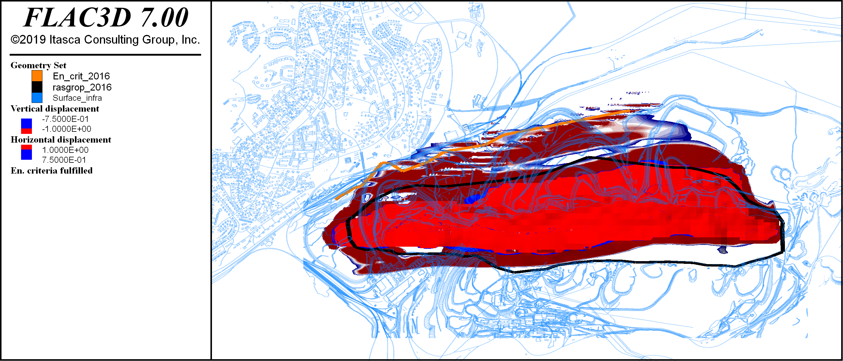
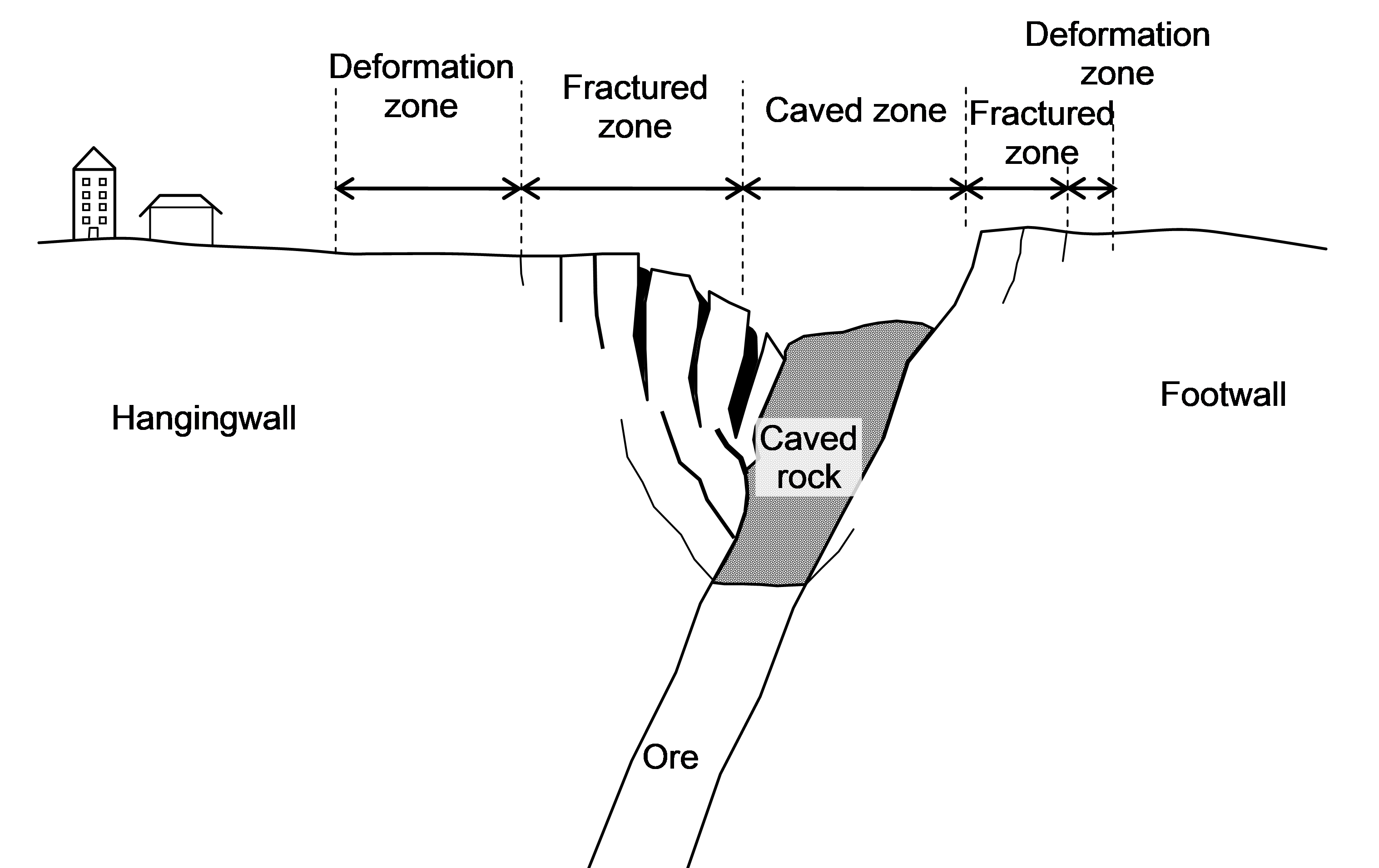
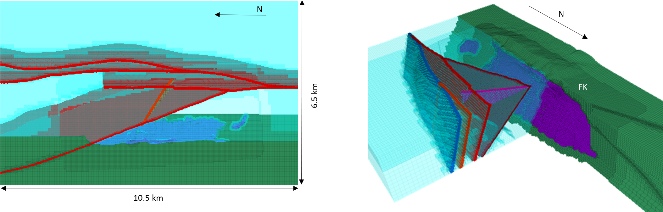
The Kiirunavaara mine is currently mining using SLC at a depth of 800–900 m from the ground surface (relative to the hangingwall top surface). With new ore reserves being identified at depth, the mine is expected to continue to mine past its current main haulage level at 1100 m depth (level 1365). To estimate the effect on the hangingwall ground surface, Itasca has been contracted to predict the ground surface effect from mining below the current haulage level, with emphasis on the influence on the city of Kiruna (Figure 1).
Model Description
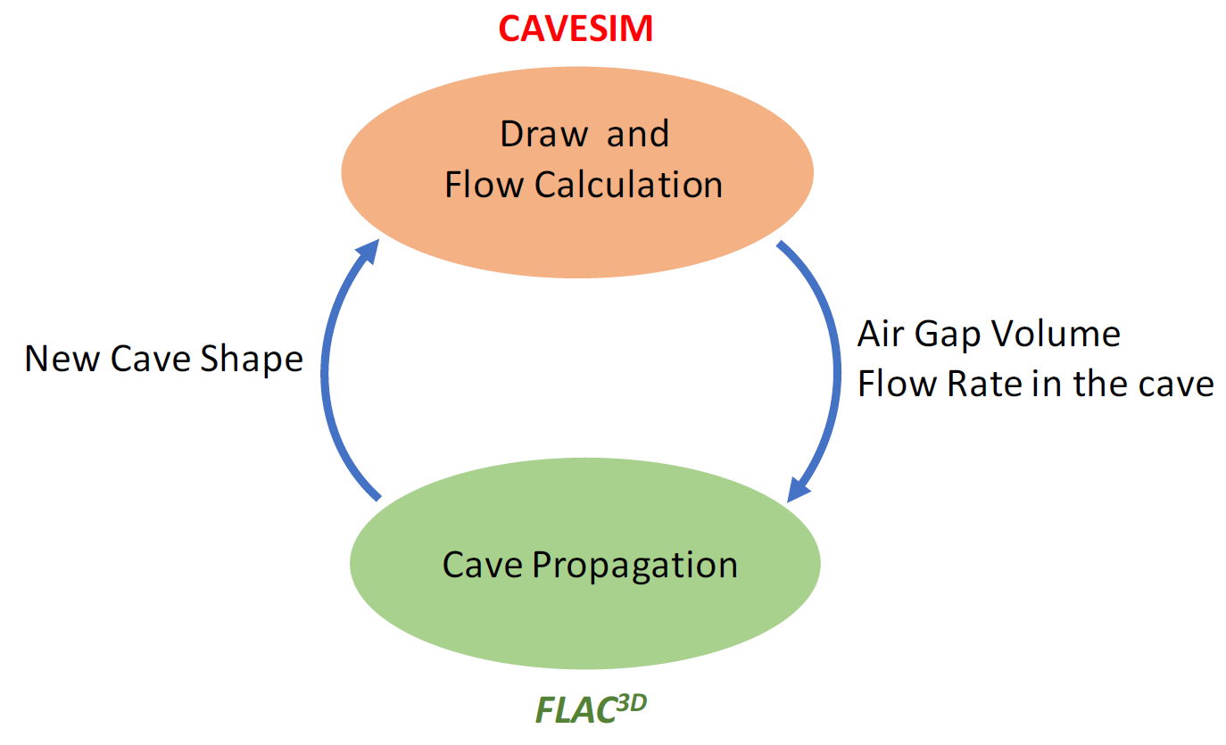
The latest generation of models used to simulate the SLC and the hangingwall caving uses a coupled approach between FLAC3D and CAVESIM. In the coupled approach, production draw and cave rock flow are explicitly modelled in CAVESIM, and the cave propagation and rock mass response to the draw are simulated in FLAC3D, see Figure 2.
The coupling is of relay type, with the two software “taking turns” to reach equilibrium for each mining stage before continuing to the next.
FLAC3D Geomechanical Model
The geomechanical response to mining is simulated by FLAC3D using a mine-scale model encompassing the entire ore body and several large-scale regional deformation zones, see Figure 3.
The FLAC3D model uses the Itasca Model for Advanced Strain Softening (IMASS) for all in-situ geological entities. This allows for realistic strain softening behavior to be modeled using input based on standardized Hoek-Brown failure criterion parameters. The coupling to CAVESIM allows a complex and detailed geomechanical model to be used for the continuum response.
Material Draw and Emergent Cave Rock Column
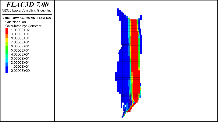
Material draw in CAVESIM is modeled on a ring-by-ring basis. The draw column from each ring interacts with the draw from adjacent rings and previously mobilized material, allowing emergent draw patterns to form inside the cave rock column, which are relayed to FLAC3D as flow rates, see Figure 4. The flow rates are then used by FLAC3D to calculate the back pressure from the cave and subsequently the stress redistribution caused by the discontinuous flow.
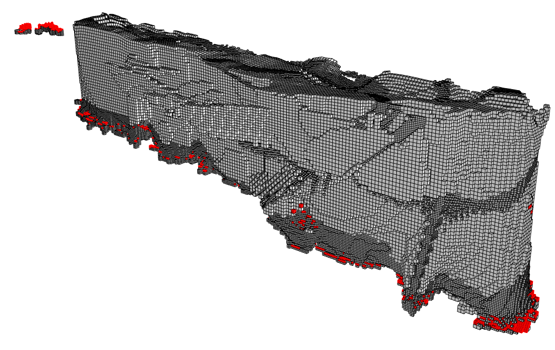
The combined information from FLAC3D and CAVESIM allows for emergent cave shapes to form based on the draw pattern and the geomechanical properties of the host and rock, see Figure 5, including airgaps from delayed caving.
The emergent cave in turn affects the deformation and stress redistribution patterns around the cave column based on the differential flow rates inside the cave, with flowing regions supplying less confinement to the cave boundary than stagnated regions.
Ground Surface Effects
The emergent cave shape and the flow-dependent confinement along the cave boundary is used by FLAC3D to calculate associated displacements and strains around the cave. These displacement patterns are compared to empirical limit lines based on ground surface observations for the two past decades. Deformation and strain limits are determined for the model using a fit for year-over-year changes between model output and field observations. The determined limits (Figure 6) are then used for forward analysis for mining according to long-term plans.